Newton's Rings
Interactive Physics Ready
Click "Run Code" to launch simulation and interactive parameter sliders.
Mathematical Problem Formulation
Theoretical Background & Explanation
Newton's Rings: Interference by Division of Amplitude
Newton's Rings represent one of the most celebrated interference phenomena in wave optics. When a plano-convex lens of large radius of curvature $R$ is placed with its curved surface on an optically flat glass plate, a variable-thickness wedge film of air or liquid is enclosed. Interference between beams reflected (or transmitted) at the top and bottom surfaces of this film creates a system of concentric circular fringes of equal thickness (Fizeau fringes).
1. Experimental Optical Bench Setup & Ray Paths
The experimental arrangement designed by Sir Isaac Newton and perfected for precision interferometry consists of the following components:
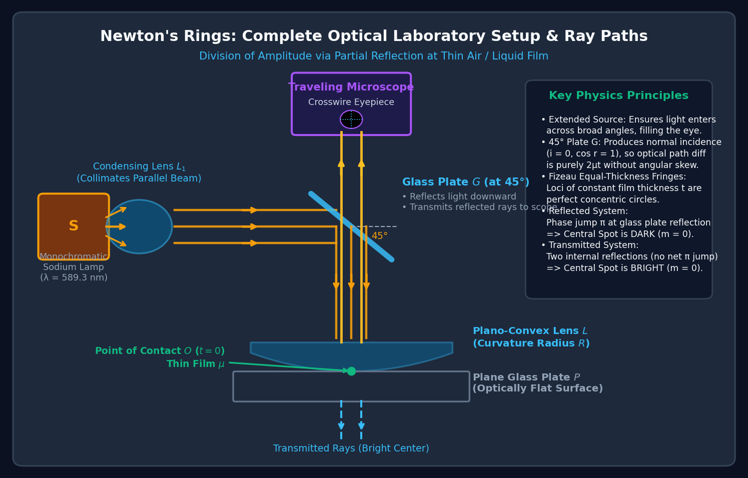
- Extended Monochromatic Source ($S$): Typically a Sodium vapor lamp emitting intense yellow light at $\lambda = 589.3\text{ nm}$ (mean of $D_1$ and $D_2$ doublet). An extended broad source is essential so that rays enter the pupil over a wide range of angles, ensuring a broad field of view.
- Condensing Lens ($L_1$): Collimates diverging rays into a broad parallel horizontal beam directed toward the beam splitter.
- Glass Plate ($G$) at $45^\circ$: Inclined at $45^\circ$ to the vertical beam axis. It partially reflects 50% of the light normally downward onto the lens-plate system ($i = 0, \cos r = 1$), eliminating angular skew. Reflected interference rays from the film pass upward through $G$ directly into the microscope.
- Plano-Convex Lens ($L$) & Plane Glass Plate ($P$): The lens has an extremely large radius of curvature ($R \sim 1\text{ to }3\text{ m}$) so the air gap thickens very gradually. The glass plate $P$ is an optical flat with surface irregularities less than $\lambda/10$.
- Traveling Microscope: Mounted vertically above plate $G$, fitted with a crosswire eyepiece and micrometer screw gauge to measure ring diameters $D_m$ with sub-millimeter precision.
2. Thin Film Geometry & Stokes' Phase Jump
Consider a sphere of radius $R$ forming the curved surface of the lens. At radial distance $r$ from the central contact point $O$, let the film thickness be $t(r)$.
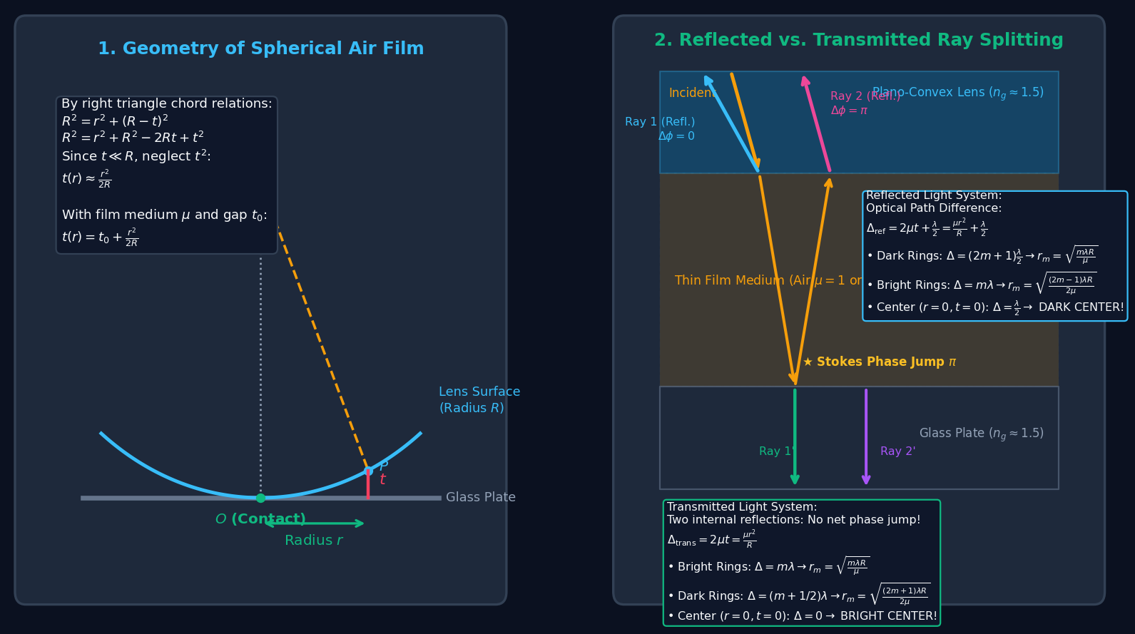
From the right-angled triangle formed with the center of curvature $C$:
Since $t \ll R$ (film thickness is typically a few micrometers while $R \sim 1\text{ m}$), the second-order term $t^2$ is negligible:
If a tiny dust particle or spacer separates the surfaces by central distance $t_0$, the total thickness is $t(r) = t_0 + \frac{r^2}{2R}$.
3. Reflected Light System: Why the Center is Pitch DARK
In the reflected system, the incident ray strikes the lens-film boundary and divides into two coherent beams:
- Ray 1: Reflected at the lower curved surface of the lens (glass of index $n_g \approx 1.5$ to air/film of index $\mu \approx 1.0$). This reflection occurs at a rarer medium interface, producing zero phase shift ($\Delta\phi_1 = 0$).
- Ray 2: Transmitted into the film, traverses distance $t$, reflects at the flat glass plate (air/film of index $\mu$ to glass of index $n_g$). This reflection occurs at a denser medium boundary. By Stokes' relations (electromagnetic boundary conditions), an abrupt phase jump of $\pi$ radians (equivalent to an optical path difference of $\lambda/2$) occurs!
Under normal incidence ($\cos r = 1$), the total effective optical path difference for reflected light is:
Dark Rings (Minima)
$$\Delta_{\text{ref}} = (2m + 1)\frac{\lambda}{2} \implies 2\mu t = m\lambda$$ $$r_m^2 = \frac{m\lambda R}{\mu} \implies r_m = \sqrt{\frac{m\lambda R}{\mu}} \quad (m = 0, 1, 2, \dots)$$For $m = 0$ at contact ($r=0, t_0=0$), $\Delta_{\text{ref}} = \lambda/2$. The waves interfere destructively, so the central spot is completely DARK!
Bright Rings (Maxima)
$$\Delta_{\text{ref}} = m\lambda \implies 2\mu t = \left(m - \frac{1}{2}\right)\lambda$$ $$r_m^2 = \frac{(2m - 1)\lambda R}{2\mu} \implies r_m = \sqrt{\frac{(2m - 1)\lambda R}{2\mu}} \quad (m = 1, 2, \dots)$$Ring diameters follow: $D_m = 2r_m \propto \sqrt{2m - 1}$.
4. Transmitted Light System: Complementary Bright Center
In the transmitted light arrangement, interference occurs between:
- Ray 1': Directly transmitted through the lens, film, and glass plate without internal reflection.
- Ray 2': Suffers two internal reflections inside the film (first at the flat plate, then at the curved lens) before emerging downward. Because both internal reflections occur at identical index steps (or because $2 \times \pi = 2\pi \equiv 0$), there is no net phase jump of $\lambda/2$!
Therefore, the effective optical path difference for transmitted rays is simply:
Bright Rings (Maxima)
$$\Delta_{\text{trans}} = m\lambda \implies 2\mu t = m\lambda \implies r_m = \sqrt{\frac{m\lambda R}{\mu}} \quad (m = 0, 1, 2, \dots)$$For $m = 0$ at contact ($r=0, t_0=0$), $\Delta_{\text{trans}} = 0$. Waves interfere constructively, so the central spot is BRIGHT!
Dark Rings (Minima)
$$\Delta_{\text{trans}} = \left(m + \frac{1}{2}\right)\lambda \implies r_m = \sqrt{\frac{(2m + 1)\lambda R}{2\mu}} \quad (m = 0, 1, 2, \dots)$$Dark ring positions in transmitted light correspond exactly to bright ring positions in reflected light!
5. Strict Complementarity & Laboratory Determination of $\lambda$ and $\mu$
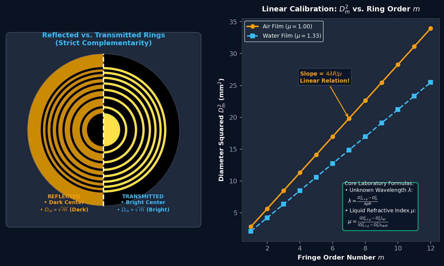
By conservation of energy, the sum of reflected and transmitted intensities satisfies $I_{\text{ref}}(r) + I_{\text{trans}}(r) = I_0$. The two fringe patterns are strictly complementary:
Why Fringes Get Closer Together (Fringe Compression)
The fringe width $\beta_m$ between consecutive rings is given by the difference in consecutive radii:
As the ring order $m$ increases, $\beta_m$ decreases inversely with $\sqrt{m}$. Thus, Newton's rings are widely spaced near the center and become progressively crowded together as $r$ increases.
Determination of Unknown Wavelength $\lambda$
Let $D_m$ and $D_{m+p}$ be the diameters of the $m$-th and $(m+p)$-th dark rings in air ($\mu = 1$). Then:
Crucial Advantage: Any zero error or central air gap $t_0$ (caused by dust or lack of perfect contact) enters equally into $D_{m+p}^2$ and $D_m^2$ and cancels out completely in the difference $(D_{m+p}^2 - D_m^2)$!
Determination of Liquid Refractive Index $\mu$
When a drop of liquid (e.g., water $\mu = 1.33$ or oil $\mu = 1.5$) is placed between the lens and plate:
Since $\mu > 1$, introducing a liquid contracts the rings, pulling them closer to the center!
6. Live Parameter Sliders Guide
Manipulate the real-time physics sliders in the workbench to witness physical wave optics in action:
- Wavelength $\lambda$ (400–750 nm): Dynamically updates the rendered spectral color (violet $\to$ cyan $\to$ green $\to$ sodium yellow $\to$ red) and expands the fringe rings ($r \propto \sqrt{\lambda}$).
- Curvature Radius $R$ (0.50–3.00 m): Flatter lenses with larger $R$ expand the ring diameters ($r \propto \sqrt{R}$), making rings easier to measure in laboratory telescopes.
- Film Refractive Index $\mu$ (1.00–1.65): Increase from $1.00$ (Air) to $1.33$ (Water) or $1.55$ (Cedar oil) to observe the immediate contraction of ring diameters ($r \propto 1/\sqrt{\mu}$).
- Air Gap $t_0$ (0–300 nm): Simulates a dust speck lifting the lens. Watch how the central dark minimum continuously transitions into a bright maximum when $t_0 = \lambda/4$ ($\approx 147\text{ nm}$).